Roof Overhang Wind Loads

Every House Needs Roof Overhangs Roof Overhang Roofing Roof Framing

Adding Roof Overhangs Fine Homebuilding Question Answer Roof Overhang Building A House Roofing

Image Result For High Wind Framing Hurricane Proof House Single Story Homes Roof

Roofing Diagram Eaves Cross Section Framing Construction Shed Plans Roof

Pin On Wall Frame

Wide Box Cornice Jpg 1800 1800

In this section we are going to demonstrate how to calculate the wind loads by using an s3d warehouse model below.
Roof overhang wind loads.

Concrete Pitched Roof Slab Edge Gutter Detail Pitched Roof Reinforced Concrete Roof

Asce 7 10 Wind Loading With Roof Overhangs Engineering Stack Exchange

How To Build The Perfect Roof Rake Ladder For A Cabin Or Tiny House Passive Solar Design Solar Technology Roof Overhang

Hurricane Retrofit Guide Gable End Overhangs Roof Sheathing Roof Damage Fascia Board

How Much Should Metal Roof Overhang Best Roof 2017 Roofing Diy Metal Roof Roofing
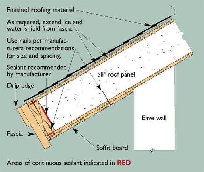
Sips More Chaleff Rogers Architects

Building A Shed Roof Canopy Fine Homebuilding Question Answer Http Www Finehomebuilding Com How To Qa Buildi Building A Shed Roof Shed Roof Building A Shed

10 Open Lean To Roof Overhang With Antique Tractor Pool Houses Barn House Barn Photos
Adding Roof Overhangs Fine Homebuilding Roof Overhang Building A House Roof

10 Convenient Hacks Metal Roofing Farmhouse Tin Roofing Overhang Green Roofing Wind Architectural Shingles Roof Roof Architecture Residential Roofing Shingles

How To Fix A Sagging Roof Line Hunker Roof Lines Roof Basement Ceiling Ideas Cheap

Fascia Board Framing Construction Roof Construction Roof Structure

What Is A Canopy Awning Which Wind Forces Should I Use To Design Engineering Express

How To Frame Flat Roofs Basic Framing Construction Flat Roof Roof Trusses Flat Roof Repair

Gable Roof Overhang Construction Google Search In 2020 Roof Framing Roof Overhang Shed Roof

Internal Gutter Google Search Metal Roof Gutter Roof Overhang

Us6209268b1 Overhang Support System For Gable Roofs Gable Roof Roof Support System
Https Www Woodworks Org Wp Content Uploads Tx Wind Workshops Hour 2 Uplift And Walls Pdf
Https Encrypted Tbn0 Gstatic Com Images Q Tbn 3aand9gcresmmacnxd Nkmhjgvnkrz6mwzlf3bagmn67b34vc Mhl2etl0 Usqp Cau

Diagram On Roof Ventilation And Soffit Venting Http Inspectapedia Com Bestpractices Figure2 55 Jpg Ventilation Design Ridge Vent Roof Design

Stall Barn With 8 X 30 Open Shed Overhang Custom Cupola With Copper Roofing Three 10 X 8 Split Sliding Doors And A Fu Open Shed Pole Barn Homes Barn Door

How To Keep Your Roof In Great Condition Gable Roof Building A Porch Decks Porches

Ddss Roof Truss In 2020 Roof Truss Design Roof Trusses Steel Trusses

Pin By Decorative Architectural Shape On Decorative Architectural Shapes Catalog Architectural Columns Architecture Pediment
Source : pinterest.com
